
Problem Set 11#
Source: Problem_Set_11_Digital_Logic Revision: n/a
Warning
The overline symbol (A̅) may be hidden in Firefox if the default zoom level is used. The symbol below should have an overline like A̅. De- or increase the zoom level if you encounter any Boolean equations.
\( \overline A \)
1#
Modify the state diagram branching conditions in the diagrams below as needed to ensure the sum and exclusion rules are obeyed in each case. You can add holding conditions or change branch codes as desired.
1.1#
Sum rule
Sum rule implies that all of the outgoing conditions from a state ored together must be True. In the following we analyze the outgoing edges for each state:
\( a_\mathrm{o} = \overline{x}\,y \lor x\,y = y \neq 1\). 2 edges.
We have two possibilities:
Introduce a holding condition: \(\overline{y}\)
We have two outgoing edges, so negate one of the outgoing conditions and overwrite the other one. For example \( \overline{x\,y} = \overline{x} \lor \overline{y}\), so substitute \(\overline{x}\,y\) for \(\overline{x} \lor \overline{y}\).
\( b_\mathrm{o} = \overline{x} \lor x = 1\). 2 edges.
\( c_\mathrm{o} = 1 \). 1 edge.
\( d_\mathrm{o} = \overline{x}\,\overline{y} \neq 1\). 2 edges.
The holding condition must be \( \overline{ \overline{x}\,\overline{y} } = x \lor y \).
\( e_\mathrm{o} = \overline{x}\,\overline{y}\,z \lor \overline{x}\,\overline{y}\,\overline{z} \lor \overline{x}\,y = \overline{x} \neq 1\). 4 edges.
The holding condition must be \( x \)
Exclusion rule
Mutual exclusion requirement implies that the outgoing edge conditions in a single a state should be mutually exclusive, in other words, one condition must not lead to more than one state.
We have to test for every condition pair if they are mutually exclusive, in other words, there should be no input condition when both of them are true. The requirement is met in every state.
1.2#
Modify the S4 branch and holding condition only.
Sum rule
\( s_\mathrm{1,o} = \overline{y}\,\overline{w} \lor w \lor \overline{x} \neq 1\). 4 edges.
The holding condition must be: \( \overline{ \overline{y}\,\overline{w} \lor w \lor \overline{x} } = (y \lor w) \land \overline{w} \land x = y\,\overline{w}\,\overline{x} \lor w\,\overline{w}\,x = y\,\overline{w}\,\overline{x} \)
Exclusion rule
The requirement is met in \(s_1\).
2#
What “to S2” branch can be added so that all possible branch conditions go to at least one state? How can the holding condition be modified to ensure there is one and only one next state for all possible branch conditions? Enter the branch conditions below.
… so that all possible branch conditions go to at least one state
This is the sum rule.
… ensure there is one and only one next state for all possible branch conditions
This is the exclusion rule.
The first problem with this graph is that the holding condition \( \overline{y}\,\overline{z} \) and the to s3 condition \( x\,\overline{y} \lor y\,\overline{z} \) are not mutually exclusive. For example for \(x=1, y=0, z=0\) both conditions are true. To create mutual exclusivity, we can add \(x=0\) as an additional condition to the holding condition and change \( \overline{y}\,\overline{z} \) to \( \overline{x}\,\overline{y}\,\overline{z} \). This condition is also mutually exclusive with to s1 condition \(\overline{x}\,z\).
Now we are searching for the to s2 condition. We could draw a K-map to visualize all the conditions. The empty cells will show the condition for the to s2 branch. Alternatively we write down the conditions to find the difference to 1:
\( x\,\overline{y} \lor y\,\overline{z} \)
\( \overline{x}\,\overline{y}\,\overline{z} \)
\( \overline{x}\,z \)
When we expand the first and third condition, we get:
\( x\, \overline{y}\, z \lor x\, \overline{y}\, \overline{z} \lor x\, y\, \overline{z} \lor \overline{x}\, y\, \overline{z} \)
\( \overline{x}\,\overline{y}\,\overline{z} \)
\( \overline{x}\, \overline{y}\, z \lor \overline{x}\, y\, z\)
If we have three variables, then we have eight minterms. The missing minterm is \(x\, y\, z\) which must be the condition to s2.
3#
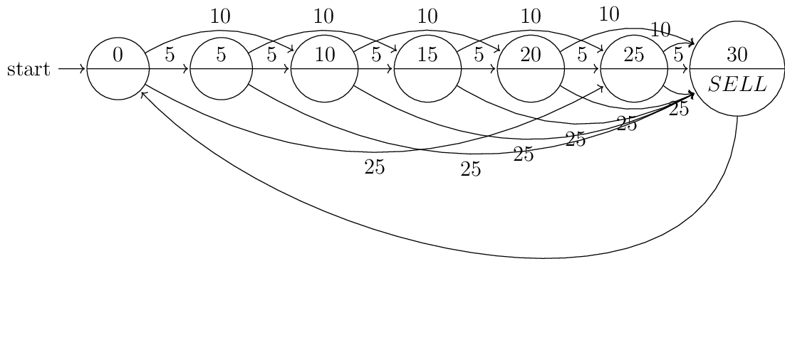
A vending machine should SELL an item if 30 cents is input. The machine has a coin sensor that can detect nickels (5 cent), dimes (10 cent), and quarters (25 cent) and reject everything else. No change is given (i.e, if two quarters are input, simply assert SELL and keep the fifty cents). Sketch a state diagram to assert SELL when adequate coinage has been inserted.
Let us assume that the coin sensor has three outputs
nickel (
5)dime (
10)quarter (
25)
and these outputs are mutually exclusive. Using this assumption we can shorten the transition conditions, e.g., instead of \(\overline{5} \land \overline{10} \land 25\) we can write just \(25\).
We draw for each 5 cent increment a single state until we reach 30 cent. The states indicate how much amount were paid. From every state there are three outgoing edges for every possible coin insert with the exception of the 30 cent state. The 30 cent state outputs SELL and after that automatically falls back to the start state. The output could be connected to a motor which revolves the product spiral once. The logic that we described corresponds to a Moore machine.
In the following machines only the state changing transitions are drawn. The rest of the conditions stay in the same state. So the machine adheres to the sum rule.
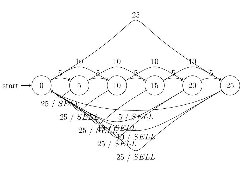
Alternatively we could eliminate the 30 cent state and output SELL whenever we return back to the start state. This logic corresponds to a Mealy machine:
4#
Sketch a Moore-model and also a Mealy-model state diagram for a sequential machine that can detect when a four-digit combination has been typed into a numeric keypad. Use last four numbers of your telephone number for a combination. A “start” button must be pressed immediately prior to entering a valid combination, and an “open” button must be pressed immediately after a valid combination. For this problem, you can assume that two buttons cannot be asserted simultaneously (i.e., if more than one button is pressed, only the signal from the first button pressed will be asserted until it is released; the second button will be asserted after the first button is released if it is still being pressed. If more than two buttons are pressed, and the first button pressed is released, then the second button pressed will be asserted until it is released, and so forth). The “Any Button” (AB) output will be asserted as soon as any button is pressed, and deasserted only when no buttons are pressed.
We can use the rising edge of the \(ab\) output to change the state. Whenever \(ab\) is active transition to another node according to the edge condition and if \(ab\) is not active, we stay in the same state. So the conditions of the state changing edges are ANDed with the \(ab\) output. The looping edges have \(\overline{ab}\) as condition. In other words, \(ab\) is used like a clock signal for the state machine.
A Moore machine that asserts the \(OK\) signal if the password correct:
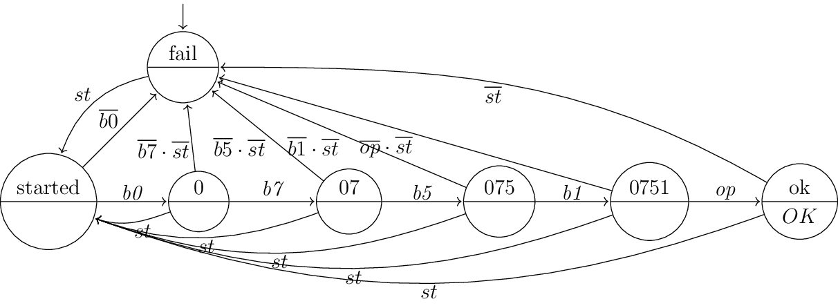
In this implementation \(OK\) signal is active as long as no button is pressed. The user can start with key entry every time using the \(st\) key.
Note
If the a rising edge of \(OK\) is enough as output, we could start with \(OK\) active and get rid of the fail state. But then we have to find another way to handle the case when the sequence is wrong. For example, if the user enters a wrong key combination, then we could jump back to started, so the key entry would begin from the beginning. But then the requirement
A “start” button must be pressed immediately prior to entering a valid combination
would be violated.
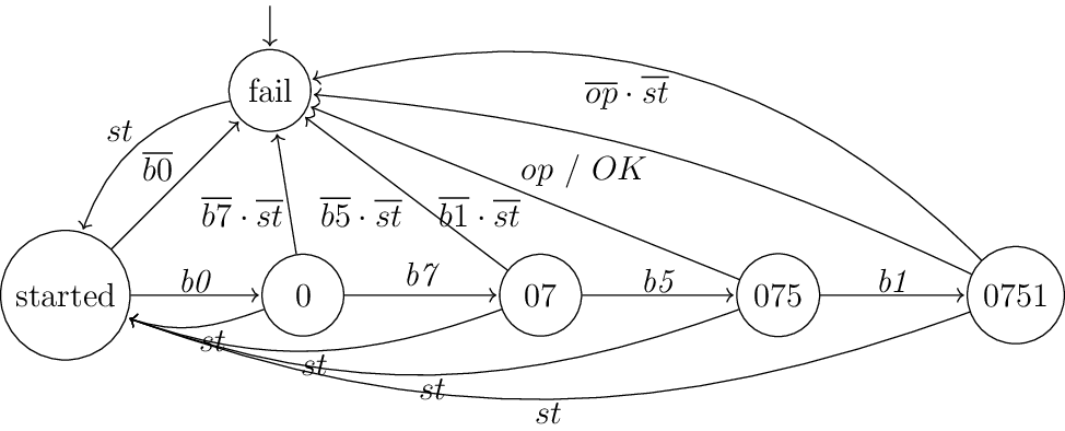
Similar to the problem 3 we can get rid of the last state for generating the \(OK\) output if we use a Mealy machine:
5#
Sketch a circuit for the state machine below.
The state diagram is a Moore machine. The states only include the active outputs, in other words if an output is not included (e.g., grn <= '1'), then this output is not active.
The K-maps on the right describe
transition logic for \(a\) and \(b\)
output logic for \(red\) and \(green\).
The logic equations are:
assign
a_ns = 1,
b_ns = (~b_ps & x) | (b_ps & y),
red = a_ps & ~b_ps,
green = b_ps;
Using the logic equations we can draw the circuit:
TODO
6#
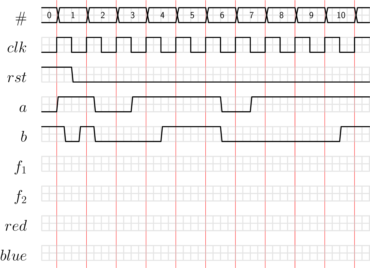
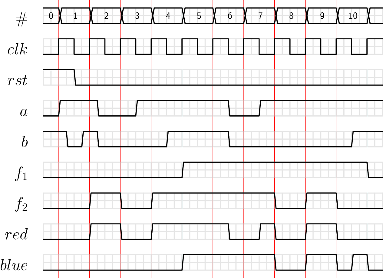
In the timing diagram below, show the time courses of the flip-flops (labeled \(f_1\) and \(f_2\)) and output signals defined by the state diagram. The states are encoded as, e.g., \(00 = f_1 f_2\).
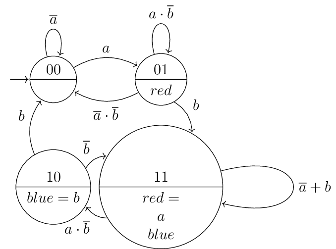
Note
The state machine drawn looks like a Moore machine because the outputs are written beside the states. At the same time we see that the state encoded with 11 activates \(red\) depending on the value of \(a\). This actually means that the output depends on the input signals, so the machine drawn is actually a Mealy machine drawn in a compact way.
In a Mealy machine drawn in a typical way we would write the state transition conditions of 11 as:
\(\overline{a} + b / blue\)
\(a + \overline{b} / blue \, red\)
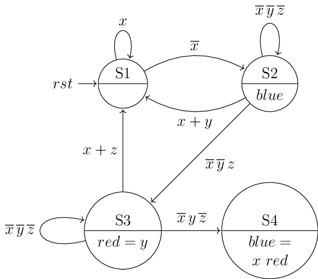
7#
Sketch a state diagram based on the following Verilog Code
module fsm (
	clk, rst, x, y, z, red, blue);
input clk, rst, x, y, z;
output red, blue;

localparam S1 = 2'd0;
localparam S2 = 2'd1;
localparam S3 = 2'd2;
localparam S4 = 2'd3;

logic [1:0] ps, ns;

always @ (ps, x, y, z) begin
	case (ps)
	S1: begin
		red = 1'b0;
		blue = 1'b0;
		if (X == 1'b0) ns = S1;
		else ns = S2;
	end
	S2: begin
		red = 1'b0;
		blue = 1'b1;
		if (X == 1'b0 && Y == 1'b0 && Z == 1'b0) ns = S2;
		else if (X == 1'b1 || Y == 1'b1) ns = S1;
		else if (Z == 1'b1 && X == 1'b0 && Y == 1'b0) ns = S3;
	end

	S3: begin
		red = Y;
		blue = 1'b0;
		if (Y == 1'b1 && X == 1'b0 && Z == 1'b0) ns = S4;
		else if (X == 1'b0 && Y == 1'b0 && Z == 1'b0) ns = S3;
		else if (X == 1'b1 || Z == 1'b1) ns = S1;
		end
	S4: begin
		red = 1'b1;
		blue = X;
		ns = S1;
		end
	default: begin
		red = 1'b0;
		blue = 1'b0;
		ns = S1;
	end
	endcase
end

always @ (clk, rst) begin
	if (rst == 1'b1) ps <= S1;
	else ps <= ns;
end
endmodule
The first always block describes the state transition logic and the second one describes the state memory.
Note
In the case statement the state will hold if none of the if case conditions is true. When drawing the state machine we have to consider that and calculate the holding condition by negating the sum of the transitions going out of a state.
Note
The state conditions in the Verilog code could also be shortened like if (x && ~y) etc, because all of the inputs are bit signals.
8#
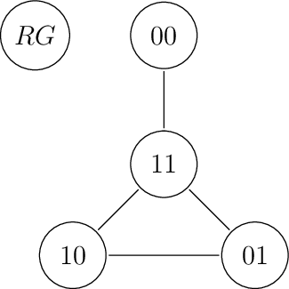
Assign state codes to the state diagrams below, using unit-distance coding and/or matching state codes to outputs.
TODO diagrams
Note
We save output logic by matching state codes to the outputs.
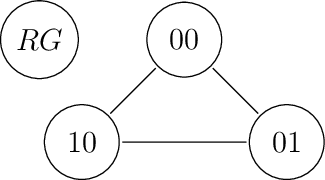
top left
We need two bits, because \(\lceil \log_{2} 3 = 2\rceil\), using matching state codes to outputs
top right
We have four states so we need at least two bits. But if we use two bits and want to use unit-distance coding, then we cannot tie \(odd\) output to a flip-flop bit:
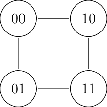
If we wanted to match a state bit to the output instead:
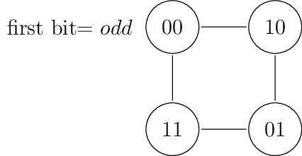
Note
The state machine seems to count the number of inputs and output \(odd\) if there are odd number of inputs. We can minimize the whole state machine to two states:
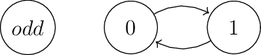
This machine has both unit-distance and matching state code.
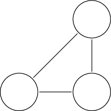
below left
Only matching state codes to outputs is possible. Unit-distance is not possible. For an explanation refer to the next automata.
below right
We have the following graph:
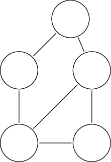
We cannot match state codes to outputs so we try unit-distance coding. Unit-distance coding does not work either, because the state diagram has three states in the right below part of the state diagram which are connected together like this:
Why? Assume that we begin with node a and find unit-distance codes for b and c. Then b and c must be at least two bits away from each other. At least ternary coding would allow unit-distance coding.
We could have used a code which changes only two bits during state transition, e.g., one-hot coding. But if we change two bits, then we do not have the advantage of unit-distance coding regarding glitches.